Flash Program ESP-01 using USB Serial Adapter. Programming ESP is a bit hard for beginners. In this tutorial, we will make it easy for you to understand the initial step so you can do it your self.
How to Flash or Program ESP-01?
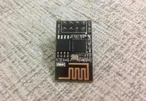
ESP-01 is a black colored module with 1024k memory. ESP-01 requires only 3.3 volts to power up. To flash or upload firmware/sketch, we need an external USB Serial Board adapter that supports 3.3 volts.
USB to Serial Board Adapters
In this tutorial, we will use 4 different kinds of Serial Board:
- ESP8266 Serial Module Board
- USB to TTL CH340G Converter Module Adapter
- FT232RL
- Arduino UNO
1. Flashing ESP-01 using Esp8266 Serial Module Board
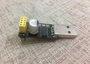
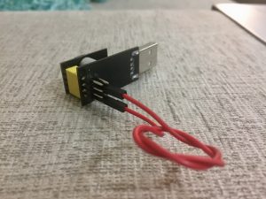
Wiring ESP-01 to set on programming mode
To set ESP-01 on programming mode, we need to set a jumper wire to Ground and Io0 (IO Zero)
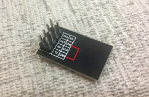
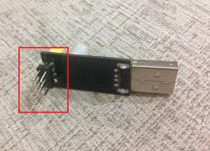
To make an easy jumper, I soldered 8 pins behind the serial module. This may help us later in testing the program after the firmware is uploaded.
How to upload sketch on ESP-01 using Arduino?
Insert the serial adapter to your computer USB port and open Arduino software. You should get “Port:” enabled. Just select the port shown on your side, in my case I got Com3. Yours may be different. If you got the port number, just select it and skip the following step and proceed to ESP-01 Arduino Board Configuration
How to get Port number manually without using Arduino Software?
If you don’t use Arduino software and just want to use other esptool for direct flashing of compiled binary bin files, you may need to find port number manually.
Go to Control Panel >> Device Manager >> Ports >>
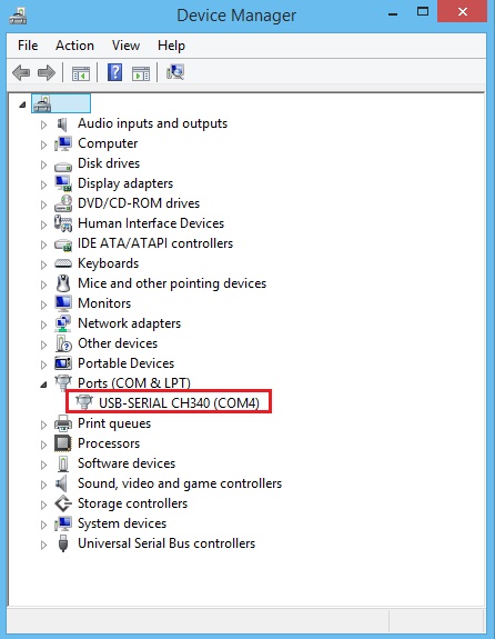
If you have more than one port showing, just remove the Serial Module from USB and see what port disappeared. Insert the USB again and look for the new port number. This how to get the port number manually.
ESP-01 Arduino Board Configuration
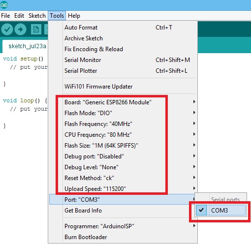
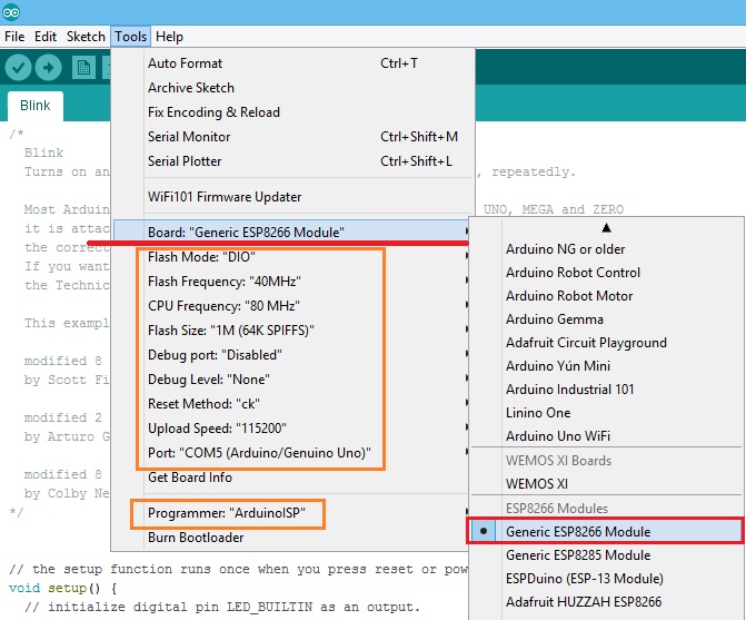
Next, select the right Board. On Arduino software click Tools >> Board: “???” >> Find Generic ESP8266 Module and select it
Now change the board settings:
- Flash Mode: “DIO”
- Flash Frequency: “40MHz”
- CPU Frequency: “80 MHz”
- Flash Size: “1M (64K SPIFFS)”
- Debug Port: “Disabled”
- Debug Level: “None”
- Reset Method: “ck”
- Upload Speed: “115200”
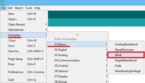
Now it’s all set. Let’s upload a sketch. Open an example sketch. Open the blink sketch on Arduino.
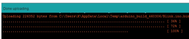
Upload the blink sketch by pressing ctrl+u or go to Sketch and click Upload. You will see a progressing dot while uploading. Sometimes uploading take a minute or two.
If you get an error like:
- warning: espcomm_sync failed
- error: espcomm_open failed
- error: espcomm_upload_mem failed
The wirings maybe not properly connected. It’s good to remove the USB first from the computer and check the wirings if properly connected and proceed again
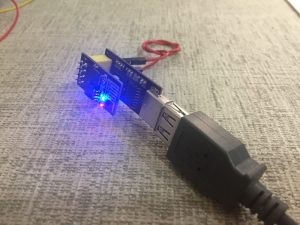
After the upload, you should see your ESP-01 blinking. You have made a successful upload.
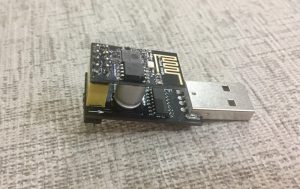
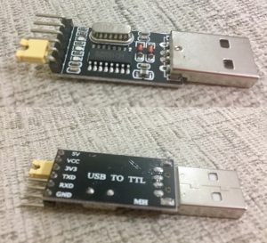
2. Flash ESP-01 using USB to TTL CH340G Converter Module Adapter
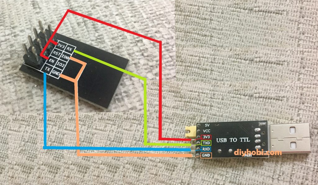
This serial adapter has a simple design but a bit complex to use in programming an ESP compare to the first one we used. It has 5v, TX, RX, GND and 3.3v which make it fit to program an ESP.
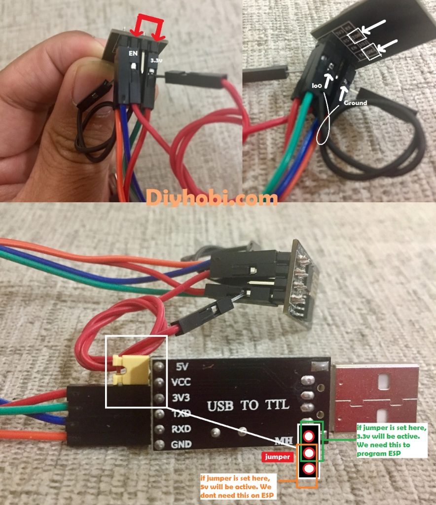
The process of flashing ESP-01 using this adapter is almost the same as the first one we used. The only addition to the process is to add a jumper wire between the 3V3 and EN of ESP. Check the image below:
Let’s see it on the actual wirings
The wiring of ESP to Serial should be:
- 3v3 – 3v3
- RX – TXD
- TX – RXD
- GND – GND
Please ensure the jumper wires are connected properly to make it work.
Again we need to select the right Board. On Arduino software click Tools >> Board: Generic ESP8266 Module
Board settings:
- Flash Mode: “DIO”
- Flash Frequency: “40MHz”
- CPU Frequency: “80 MHz”
- Flash Size: “1M (64K SPIFFS)”
- Debug Port: “Disabled”
- Debug Level: “None”
- Reset Method: “ck”
- Upload Speed: “115200”
Now we are ready to start an upload.
3. Flash ESP-01 using USB to TTL CH340G Converter Module Adapter
Using TTL CH340G adapter to program ESP is the same as the process we had discussed above. RX should be connected to TX and TX to RX. Just dont forget to always use 3.3v to power up the ESP.

Again we need to select the right Board. On Arduino software click Tools >> Board: Generic ESP8266 Module
Board settings are the same as the previous one:
- Flash Mode: “DIO”
- Flash Frequency: “40MHz”
- CPU Frequency: “80 MHz”
- Flash Size: “1M (64K SPIFFS)”
- Debug Port: “Disabled”
- Debug Level: “None”
- Reset Method: “ck”
- Upload Speed: “115200”
Now we are ready to upload a sketch
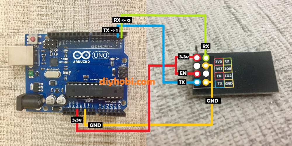
4. Flash ESP-01 using Arduino Uno
Arduino Uno is the very commonly used to flash/program the ESP.
- Esp RX is going to Uno Rx <-0
- Esp Tx going to Uno Tx->1.
- Esp 3.3v+EN to Uno 3.3v
- GND+Io0 to GND.
One final thing is the board settings of Arduino software. Go to Tools >> Board >> Select NOT Arduino UNO but select Generic ESP8266 Module.
And ensure you have these settings:
- Flash Mode: “DIO”
- Flash Frequency: “40MHz”
- CPU Frequency: “80 MHz”
- Flash Size: “1M (64K SPIFFS)”
- Debug Port: “Disabled”
- Debug Level: “None”
- Reset Method: “ck”
- Upload Speed: “115200”
Hi
very good document,
I tried it , also various ways, but did not succeed.
any hints maybe?
I am trying this for ages.
with Serial Cable, with Arduino not working for me.
Arduino: 1.8.4 (Linux), Board: “Generic ESP8266 Module, 80 MHz, 40MHz, DIO, 115200, 512K (64K SPIFFS), ck, Disabled, None”
Archiving built core (caching) in: /tmp/arduino_cache_680681/core/core_esp8266_esp8266_generic_CpuFrequency_80,FlashFreq_40,FlashMode_dio,UploadSpeed_115200,FlashSize_512K64,ResetMethod_ck,Debug_Disabled,DebugLevel_None_____0787bcf546011aea495b3e93767e5a20.a
Sketch uses 229849 bytes (52%) of program storage space. Maximum is 434160 bytes.
Global variables use 32112 bytes (39%) of dynamic memory, leaving 49808 bytes for local variables. Maximum is 81920 bytes.
/home/zwh100/.arduino15/packages/esp8266/tools/esptool/0.4.9/esptool -vv -cd ck -cb 115200 -cp /dev/ttyUSB0 -ca 0x00000 -cf /tmp/arduino_build_253007/ESP8266_webserser_esay_ledonoff.ino.bin
esptool v0.4.9 – (c) 2014 Ch. Klippel
setting board to ck
setting baudrate from 115200 to 115200
setting port from /dev/ttyUSB0 to /dev/ttyUSB0
setting address from 0x00000000 to 0x00000000
espcomm_upload_file
espcomm_upload_mem
opening port /dev/ttyUSB0 at 115200
tcgetattr
tcsetattr
serial open
opening bootloader
resetting board
trying to connect
espcomm_send_command: sending command header
espcomm_send_command: sending command payload
trying to connect
espcomm_send_command: sending command header
espcomm_send_command: sending command payload
trying to connect
espcomm_send_command: sending command header
espcomm_send_command: sending command payload
warning: espcomm_sync failed
error: espcomm_open failed
error: espcomm_upload_mem failed
error: espcomm_upload_mem failed
This report would have more information with
“Show verbose output during compilation”
option enabled in File -> Preferences.
Thanks you for the nice explanation , i am facing one issue ..
i try with method 2 and 3 and it’s the same …
whenever i flashing the program all working great until i desconnect it , it just forget it all .
like never programmed ..
i really don’t understand what i am missing !
never mind i learn that i need to disconnect GPIO0 when need to run it in a stand alone …